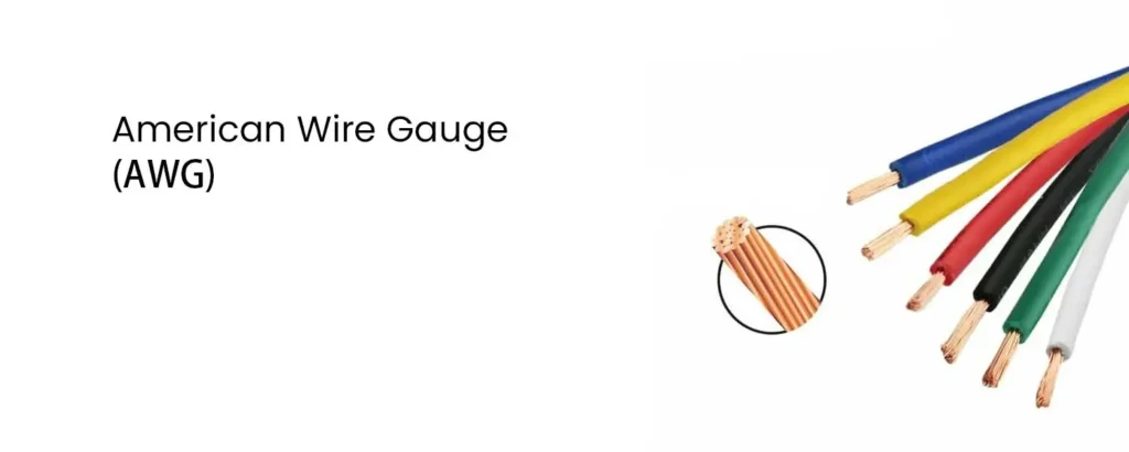
The American Wire Gauge (AWG) system, established in 1857, is a standardized method for measuring the diameters of round, solid, non-ferrous electrical wires used primarily in North America.
Key characteristics of AWG:
- Logarithmic System: Increasing gauge numbers signify decreasing wire diameters, similar to other non-metric gauges.
- Distinct from Metric System: AWG differs from IEC 60228, the metric standard used globally, which directly relates to the wire’s cross-sectional area in square millimeters (mm²).
- Historical Origin: AWG originated from the number of drawing processes needed to produce a specific wire gauge. Thinner wires (higher gauge numbers) required more passes through drawing dies.
- Standardization Benefit: AWG’s development replaced proprietary wire gauge systems, simplifying wire selection for various applications.
Important Notes:
- AWG tables are for single, solid, round conductors.
- Stranded wire AWG is determined by the equivalent solid conductor’s cross-sectional area. Due to gaps between strands, stranded wires have slightly larger diameters than solid wires with the same AWG.
- While functionally interchangeable with the Brown & Sharpe (B&S) gauge for sheet metal, using B&S for wires is technically incorrect.
- AWG is occasionally used to measure non-metallic body piercing jewelry sizes, especially for smaller gauges.
In summary, AWG remains a prominent system for specifying wire diameters in North America, but it’s crucial to understand its differences from the metric system and its limitations when dealing with stranded wires.
Understanding AWG Gauge Sizes and Calculations
This section delves deeper into the technical aspects of the American Wire Gauge (AWG) system, providing details on:
Diameter and Area Relationship:
- AWG gauges have decreasing diameters with increasing gauge numbers.
- The ratio of diameters between consecutive gauges is approximately 1.12293.
- Each gauge size has a constant multiple increase in cross-sectional area compared to the previous one.
Formula for Diameter:
- The diameter of an AWG wire can be calculated using the formula:
d = 0.005 inch * 92^(36 - n) / 39(in inches)d = 0.127 mm * 92^(36 - n) / 39(in millimeters)
nrepresents the AWG size (36 to 0) for standard gauges and -1, -2, -3 for sizes 00, 000, and 0000, respectively.
Formula for Gauge from Diameter:
- The AWG gauge can be calculated from the diameter using:
n = -39 * log92(d / 0.005 inch) + 36(in inches)n = -39 * log92(d / 0.127 mm) + 36(in millimeters)
Cross-Sectional Area:
- The cross-sectional area of an AWG wire can be calculated using:
A ≈ 0.000019635 inch² * 92^(36 - n) / 19.5(in inches²)A ≈ 0.012668 mm² * 92^(36 - n) / 19.5(in mm²)
Key Points:
- Standard ASTM B258-02 defines the ratio between consecutive sizes as the 39th root of 92, which is approximately 1.1229322.
- Wire diameters are tabulated with a specific precision depending on the gauge size.
- Sizes with multiple zeros are larger than No. 0 and denoted using “number of zeros/0” (e.g., 4/0 for 0000).
Rules of Thumb:
- Doubling the cross-sectional area decreases the AWG by 3 (e.g., 2 No. 14 AWG wires ≈ 1 No. 11 AWG wire).
- Doubling the diameter decreases the AWG by 6 (e.g., No. 2 AWG ≈ 2x diameter of No. 8 AWG).
- Decreasing the gauge by 10 (e.g., No. 12 to No. 2) increases the area and weight by 10x and reduces resistance by 10x.
- Aluminum wire with the same cross-section as copper wire has about 61% conductivity, so it needs to be 2 AWG sizes smaller (62.9% area) to have similar resistance.
- A solid 18 AWG wire is about 1 mm in diameter.
AWG Table with Detailed Information
| AWG | Diameter of Solid Cinductor | Conductor Area | |||
| Normal | MIn | Normal | 0.98 | 0.97 | |
| Min | MIn | ||||
| Mm | Mm | Mm2 | mm2 | Mm2 | |
| 1 | 7.348 | 7.27 | 42.41 | 41.56 | - |
| 2 | 6.544 | 6.48 | 33.62 | 32.95 | - |
| 3 | 5.827 | 5.77 | 26.67 | 26.14 | - |
| 4 | 5.189 | 5.14 | 21.15 | 20.73 | - |
| 5 | 4.621 | 4.57 | 16.77 | 16.43 | - |
| 6 | 4.115 | 4.07 | 13.30 | 13.03 | - |
| 7 | 3.665 | 3.63 | 10.55 | 10.34 | - |
| 8 | 3.264 | 3.23 | 8.367 | 8.30 | - |
| 9 | 2.906 | 2.88 | 6.631 | 6.50 | - |
| 10 | 2.588 | 2.56 | 5.261 | 5.16 | 5.103 |
| 11 | 2.305 | 2.28 | 4.17 | 4.09 | 4.04 |
| 12 | 2.053 | 2.03 | 3.31 | 3.24 | 3.21 |
| 13 | 1.828 | 1.81 | 2.63 | 2.58 | 2.55 |
| 14 | 1.628 | 1.613 | 2.08 | 2.04 | 2.02 |
| 15 | 1.450 | 1.435 | 1.65 | 1.62 | 1.60 |
| 16 | 1.291 | 1.278 | 1.31 | 1.28 | 1.27 |
| 17 | 1.150 | 1.14 | 1.04 | 1.02 | 1.01 |
| 18 | 1.024 | 1.016 | 0.823 | 0.807 | 0.798 |
| 19 | 0.912 | 0.904 | 0.653 | 0.641 | 0.633 |
| 20 | 0.812 | 0.805 | 0.519 | 0.509 | 0.503 |
| 21 | 0.723 | 0.717 | 0.412 | 0.404 | 0.400 |
| 22 | 0.644 | 0.637 | 0.324 | 0.318 | 0.314 |
| 23 | 0.573 | 0.568 | 0.259 | 0.254 | 0.251 |
| 24 | 0.511 | 0.506 | 0.205 | 0.201 | 0.199 |
| 25 | 0.455 | 0.450 | 0.162 | 0.159 | - |
| 26 | 0.405 | 0.399 | 0.128 | 0.126 | - |
| 27 | 0.361 | 0.358 | 0.102 | 0.100 | - |
| 28 | 0.321 | 0.318 | 0.0804 | 0.0790 | - |
| 29 | 0.286 | 0.284 | 0.0647 | 0.0633 | - |
| 30 | 0.255 | 0.251 | 0.0507 | 0.0497 | - |
| 31 | 0.227 | 0.224 | 0.0401 | 0.0393 | - |
| 32 | 0.202 | 0.201 | 0.0324 | 0.0318 | - |
| 33 | 0.180 | 0.179 | 0.0255 | 0.0250 | - |
| 34 | 0.160 | 0.158 | 0.020 | 0.0197 | - |
| 35 | 0.143 | 0.141 | 0.0159 | 0.0156 | - |
| 36 | 0.127 | 0.126 | 0.0127 | 0.0124 | - |
| 37 | 0.113 | 0.113 | 0.0103 | 0.0100 | - |
| 38 | 0.101 | 0.101 | 0.00811 | 0.00796 | - |
| 39 | 0.0897 | 0.088 | 0.00621 | 0.00603 | - |
| 40 | 0.0799 | 0.078 | 0.00487 | 0.00477 | - |